Substation Grounding Design: Reducing Step and Touch Voltage Hazards
By David Lewis, Contributor
Substations, switchyards, generation sites, and many industrial facilities have a grounding system that consists of a buried network of ground electrodes. Grounding systems are an important part of the power infrastructure and provide multiple purposes including:
- Helping to ensure personnel and public safety
- Facilitating proper equipment operation under normal and faulted conditions
- Preventing or reducing equipment damage or fault escalation from a power system fault
- Preventing or reducing equipment damage from lightning effects
A grounding study is performed to evaluate a grounding system’s ability to reduce hazards for personnel and support power system reliability.

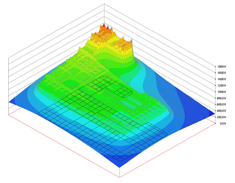
Figure 1: During a ground fault, current flows into or out of a grounding system and the electrical potential of the grounding system and surrounding soil are elevated relative to remote earth.
Ground Design Concepts
During a ground fault, current flows into or out of a grounding system and the electrical potential of the grounding system and surrounding soil are elevated relative to remote earth. This is referred to as the ground (earth) potential rise, and is illustrated in the image below:
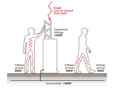
Bonding and grounding equipment at a site elevates all metallic objects to the ground potential rise. Knowing that current will travel in all available paths, sufficient voltage gradients may be present on the earth’s surface to produce catastrophic current to flow through personnel or the public within the affected area. These hazardous conditions arise as voltage varies from equipment to various points of the soil, characterized as touch voltage or step voltage hazards.
As illustrated above, a touch voltage is defined as the potential between the ground potential rise of equipment and the surface potential at the point where a person could be standing while in contact with the equipment. A step voltage is simply the difference in surface potential that could be experienced by a person bridging a distance of 1 m (3’) with their feet.

Figure 2: These hazardous conditions arise as voltage varies from equipment to various points of the soil, characterized as touch voltage or step voltage hazards.
Grounding System Analysis & Design
A grounding system analysis or study is the evaluation of the grounding system in meeting its design objectives. In the power industry, the primary focus is addressing the aspect of personnel and public safety. IEEE Std 80 provides guidance for safety related to grounding in AC substations. This standard highlights the dangerous conditions that may occur during a ground fault that can severely or fatally injure individuals in the area or in contact with metallic objects. Grounding system analysis and design represent an engineered control of hazards, as it is impossible to eliminate the risk.
A lower grounding system impedance results in a lower ground potential rise, but designing to a specific impedance, such as 5 ohms or less, is not a measure of an effective grounding system for personnel safety. Determining the touch and step voltages that may occur at a grounding system, compared to the allowable limits, is the correct measure of a grounding system efficacy. Generally, three variables drive the grounding system performance:
- Grounding system physical design and geometry
- Soil electrical characteristics
- Ground fault current magnitude and duration
It is important to note that each component is complex, often varying over time, and significantly affects the conclusions of a grounding analysis. Engineers performing a grounding system study must consider the accuracy of the data and how changes in these variables can affect a study’s conclusion. In addition, the design must verify that all equipment is bonded, size the equipment and below grade ground conductors, and possibly evaluate effects on adjacent facilities.
Where analysis indicates allowable voltages are exceeding tolerable magnitudes, there are many approaches to mitigate, such as:
- Expanding or increasing the grounding system to reduce the ground potential rise.
- Installing additional grounding conductor to reduce voltage differences on the soil surface and equipment.
- Adding or expanding a high resistivity surfacing layer material, such as crushed clean gravel or asphalt, to reduce current through the individual on the surfacing.
- Accelerating the clearing time of protective settings to reduce the duration of shock.
- Adding physical barriers to limit access to possible hazardous locations.
- Using personal protective equipment to create equipotential zones and/or increase personnel resistance.
Every station is unique, and the correct approach is an engineering design decision to reduce hazards and limit risks. The IEEE Std 80 was developed for personnel safety within AC substations, but this guide provides the physics and concepts behind grounding system analysis. These concepts are often considered when looking at generation sites, industrial facilities, transmission corridors, and other workplaces to support better studies and promote engineered controls for shock hazards.
David Lewis P.E. is a Grounding and Power Systems Engineer at EasyPower (www.easypower.com) focusing on electrical studies for power transmission and distribution system analysis. He has experience in various infrastructure studies including substation and facility grounding studies, Arc Flash analysis, and AC electromagnetic interference studies for systems up to 345 kV.
Share on Socials!
All Signs Point to Required Labeling as Key Component of Electrical Workplace Safety
Six Electrical Safety Tips for Construction Workers
Arc Flash PPE 101: Q&A with National Safety Apparel
Leaders in Electrical Safety
• Aramark
• Bowtie Engineering
• Enespro
• Ericson
• I-Gard Corporation
• IRISS
• KERMEL, INC.
• Lakeland Industries
• MELTRIC Corporation
• National Safety Apparel
• National Technology Transfer
• Oberon
• Saf-T-Gard
• SEAM Group
Subscribe!
Sign up to receive our industry publications for FREE!


